Circuit Board Projects
Circuit Board Projects
AND-OR Combination Circuit
🔎 Summary
This circuit lights the LED if either both A and B are ON at the same time, or if at least one of C or D is ON.
The AND gate section makes it so A and B must both be 1 to contribute.
The OR gate section means C or D can individually turn the LED on.
The final OR gate combines both conditions.
In other words:
LED turns on if (A AND B) OR (C OR D) is true.
LED turns off only when A=0, B=0, C=0, and D=0 or when A/B don’t both match.
📊 Truth Table
Here’s the full table of values for all switches:
| A | B | C | D | AND (A·B) | OR (C+D) | Final Output F | LED |
|---|---|---|---|---|---|---|---|
| 0 | 0 | 0 | 0 | 0 | 0 | 0 | OFF |
| 0 | 0 | 0 | 1 | 0 | 1 | 1 | ON |
| 0 | 0 | 1 | 0 | 0 | 1 | 1 | ON |
| 0 | 0 | 1 | 1 | 0 | 1 | 1 | ON |
| 0 | 1 | 0 | 0 | 0 | 0 | 0 | OFF |
| 0 | 1 | 0 | 1 | 0 | 1 | 1 | ON |
| 0 | 1 | 1 | 0 | 0 | 1 | 1 | ON |
| 0 | 1 | 1 | 1 | 0 | 1 | 1 | ON |
| 1 | 0 | 0 | 0 | 0 | 0 | 0 | OFF |
| 1 | 0 | 0 | 1 | 0 | 1 | 1 | ON |
| 1 | 0 | 1 | 0 | 0 | 1 | 1 | ON |
| 1 | 0 | 1 | 1 | 0 | 1 | 1 | ON |
| 1 | 1 | 0 | 0 | 1 | 0 | 1 | ON |
| 1 | 1 | 0 | 1 | 1 | 1 | 1 | ON |
| 1 | 1 | 1 | 0 | 1 | 1 | 1 | ON |
| 1 | 1 | 1 | 1 | 1 | 1 | 1 | ON |
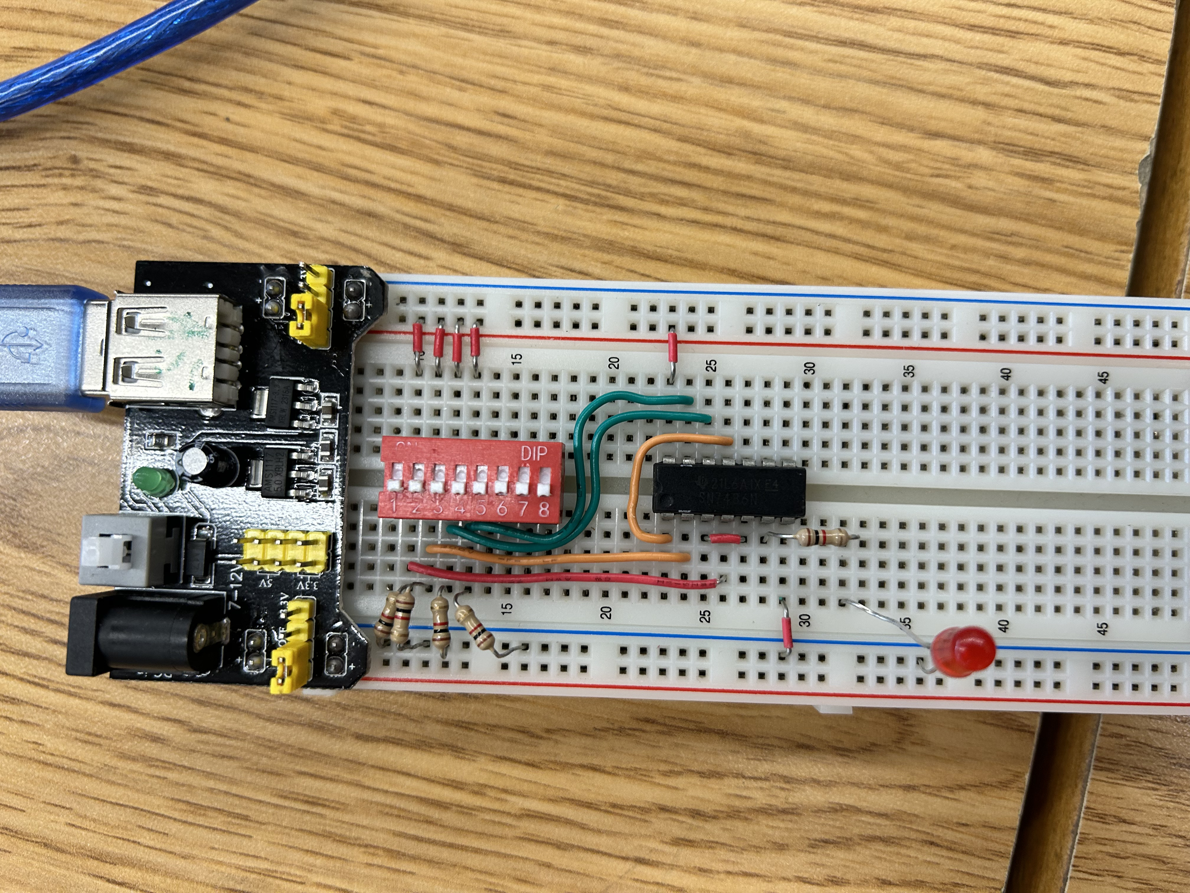
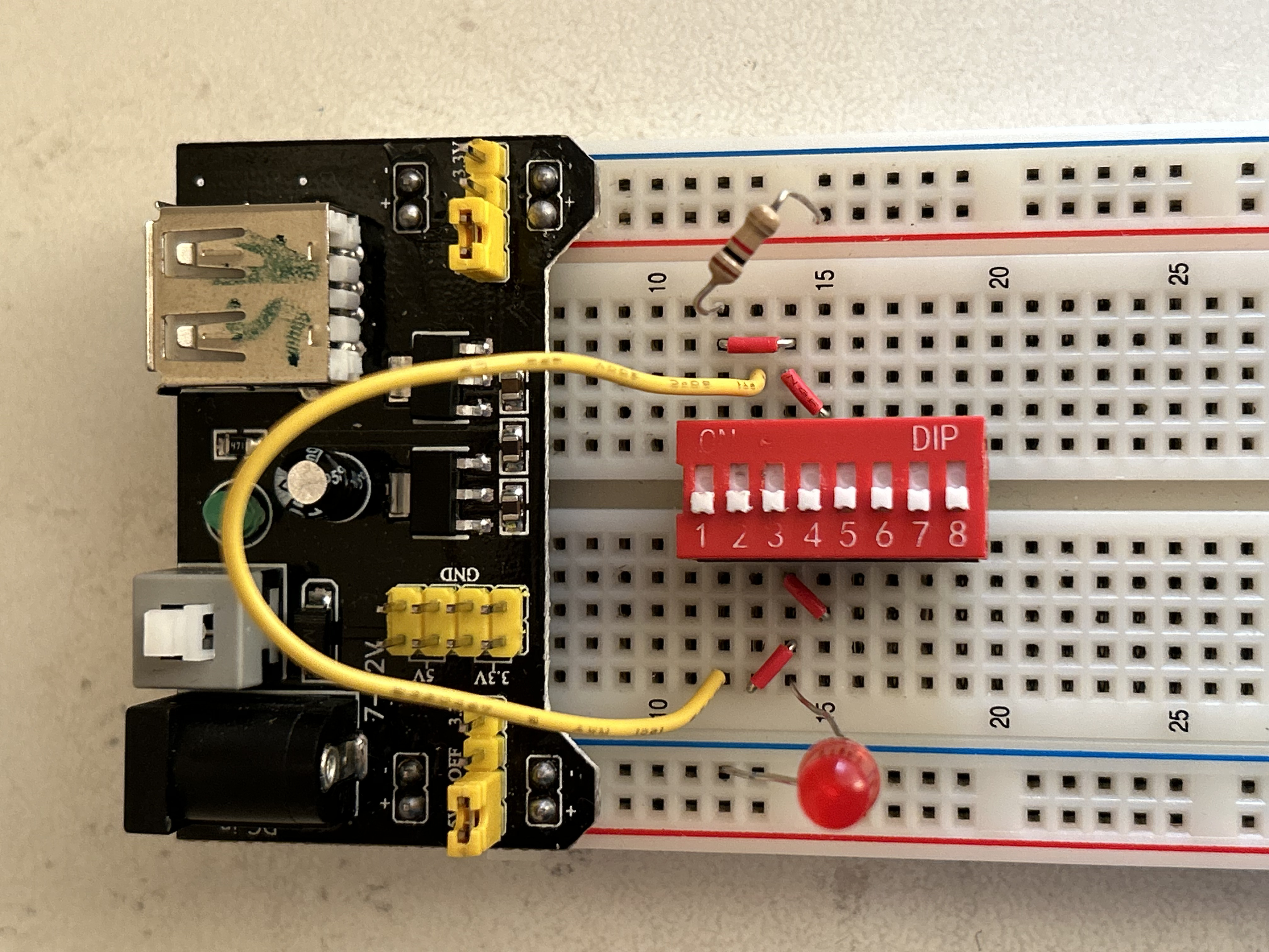 IRL Circuit Image
 Gif representation of truth table
Half-Adder
🔎 Summary
The half adder uses two inputs (A and B) that feed into:
An XOR gate → output = A ⊕ B → this is the Sum (S)
An AND gate → output = A · B → this is the Carry (C)
The two outputs are separate:
Sum (S) represents the addition result for the current bit.
Carry (C) represents a carry to the next higher bit if both inputs are 1.
The final logic expressions are:
Sum S=A⊕B Carry 𝐶=𝐴⋅𝐵
The half adder cannot handle carry input from a previous addition (unlike a full adder). Effectively:
Sum LED lights when exactly one input is ON.
Carry LED lights only when both inputs are ON.
📊 Truth Table
| A | B | Carry (C) | Sum (S) |
|---|---|---|---|
| 0 | 0 | 0 | 0 |
| 0 | 1 | 0 | 1 |
| 1 | 0 | 0 | 1 |
| 1 | 1 | 1 | 0 |
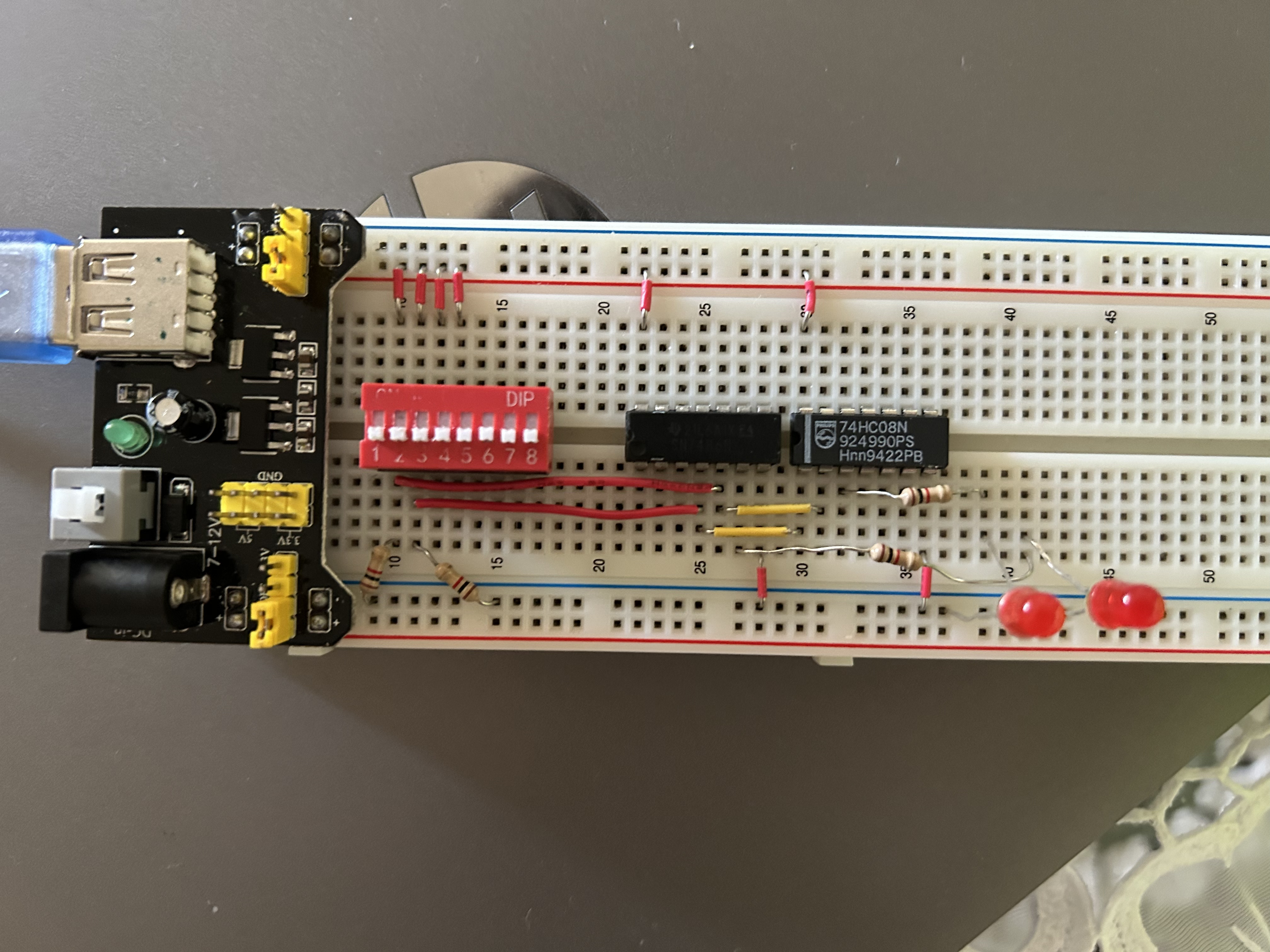 IRL Circuit Image
Video of Circuit IRL
 Gif representation of truth table
4-input XOR chain
🔎 Summary
Your circuit has 4 switches: A, B, C, and D.
Step 1: Switches A and B go into an XOR gate → output = A ⊕ B.
Step 2: That output goes into another XOR gate with input C → (A ⊕ B) ⊕ C.
Step 3: That output goes into a final XOR gate with input D → (A ⊕ B ⊕ C ⊕ D).
Step 4: The result drives the light bulb (LED).
✨ Key property: The LED shows the parity of the number of ON switches.
If an odd number of switches are ON → LED is ON.
If an even number of switches are ON → LED is OFF.
The final logic expression is:
F=A⊕B⊕C⊕D
So effectively, flicking any single switch will toggle the LED’s state.
📊 Truth Table
| A | B | C | D | Output (F) | LED |
|---|---|---|---|---|---|
| 0 | 0 | 0 | 0 | 0 | OFF |
| 0 | 0 | 0 | 1 | 1 | ON |
| 0 | 0 | 1 | 0 | 1 | ON |
| 0 | 0 | 1 | 1 | 0 | OFF |
| 0 | 1 | 0 | 0 | 1 | ON |
| 0 | 1 | 0 | 1 | 0 | OFF |
| 0 | 1 | 1 | 0 | 0 | OFF |
| 0 | 1 | 1 | 1 | 1 | ON |
| 1 | 0 | 0 | 0 | 1 | ON |
| 1 | 0 | 0 | 1 | 0 | OFF |
| 1 | 0 | 1 | 0 | 0 | OFF |
| 1 | 0 | 1 | 1 | 1 | ON |
| 1 | 1 | 0 | 0 | 0 | OFF |
| 1 | 1 | 0 | 1 | 1 | ON |
| 1 | 1 | 1 | 0 | 1 | ON |
| 1 | 1 | 1 | 1 | 0 | OFF |
 IRL Circuit Image
 Gif representation of truth table